
Category
Opportunity Space
Robot CG is important for these reasons:
- Product is a very tall and heavy robot
- If the robot falls (or is pushed) it can damage itself and/or harm customer
- If CG is improperly balanced, driven wheels can slip and cause odometry/navigation errors
- CAD is a good CG approximation, but not always accurate
- Previous method for calculating actual CG were inaccurate and laborsome
- Using 4 scales to measure normal force on the wheels and manually calculating
- Scales tended to be +/-0.3kg
Design Requirements
- Scale should support:
- One robot drivetrain worth of space (preferably more)
- Loads up to at least 250kg
2. Scale should accurately report:
- Total Mass in kg
- Center of Mass in X/Y coordinates in metric units (cm, mm)
3. Scale should be able to be “tared” or zero
4. Output should be readable and understandable by humans Loads should be able to be easily loaded on and off of the scale
Design Theory
a brief overview….
If we know all the reactions R0, R1, R2, and R3, we can find force F=R0+R1+R2+R3
If we know the length and width of the plate, then we can calculate the center of gravity as
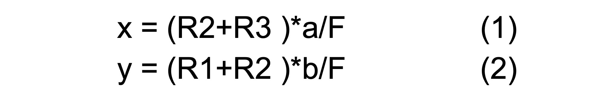
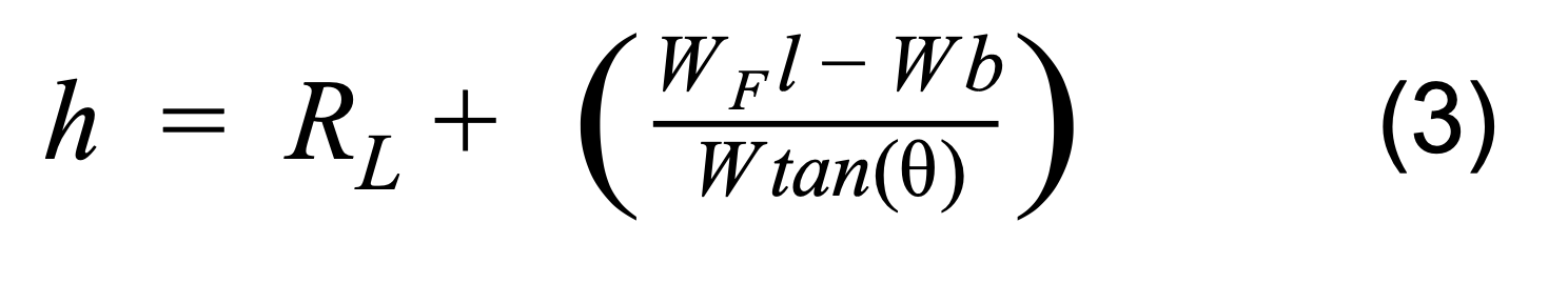
Z Center of Gravity
To find the height of the center of gravity we can tilt the platform by a known angle and then measuring the new COG again and figuring out the COG in 3D using transformations.
CAD Design
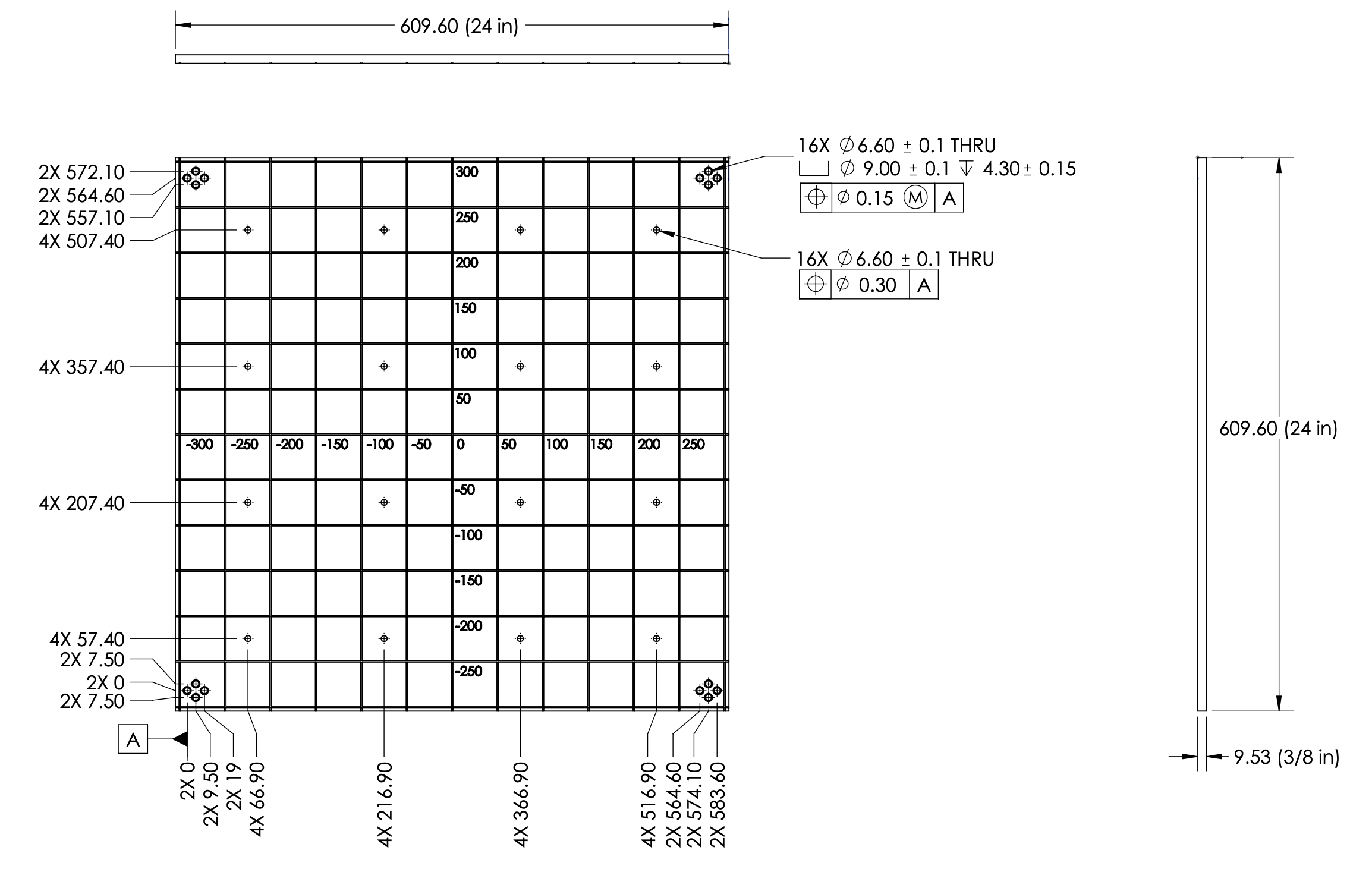
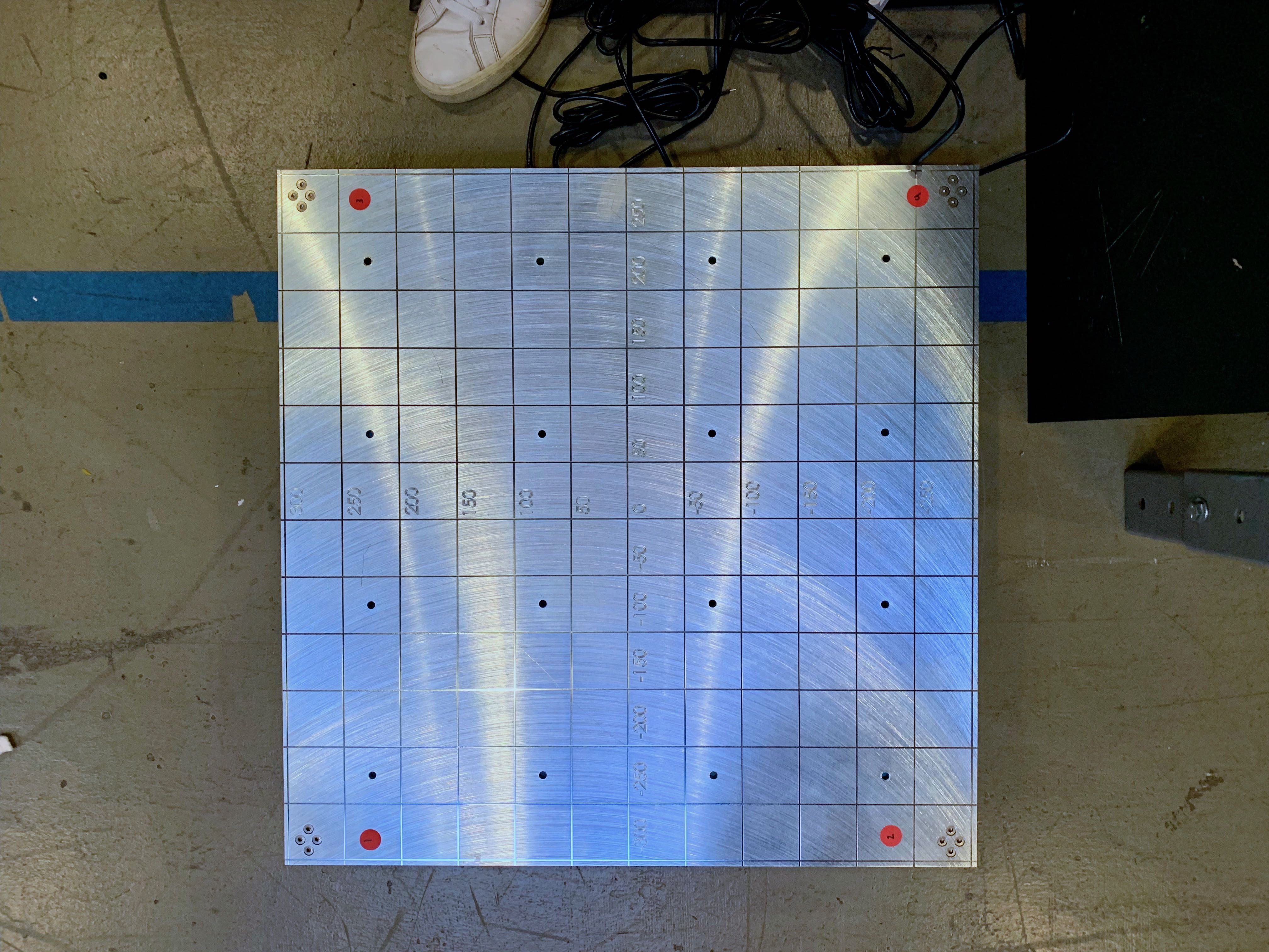
Top Plate
- 16 pattern holes
- 4 sets of 4 counterbored strain gage mounting holes
- Measurement guide every 50 mm
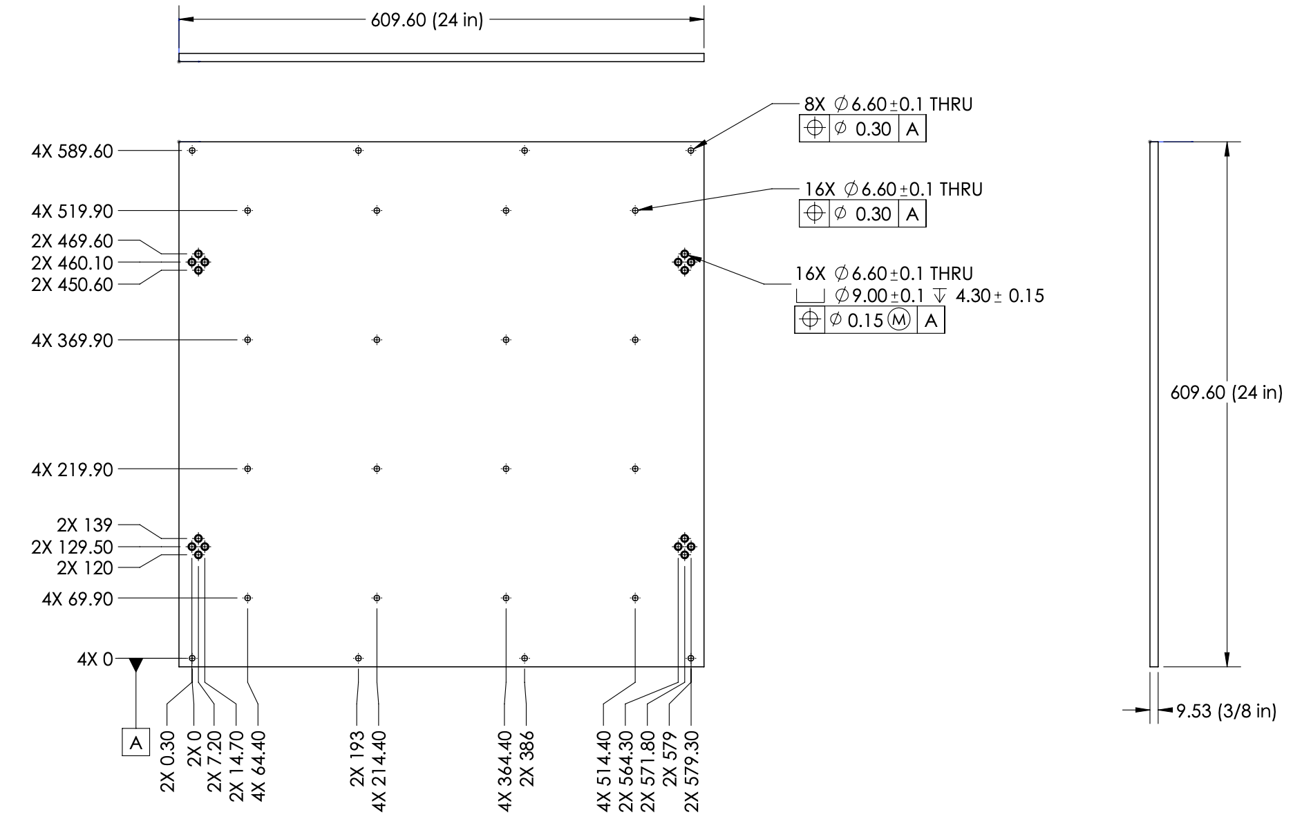
Bottom Plate
- 4 sets of 4 counterbored strain gage mounting holes
- Datum from mounting hole to reduce cost, GD&T restricts mounting hole pattern position to ensure assembly
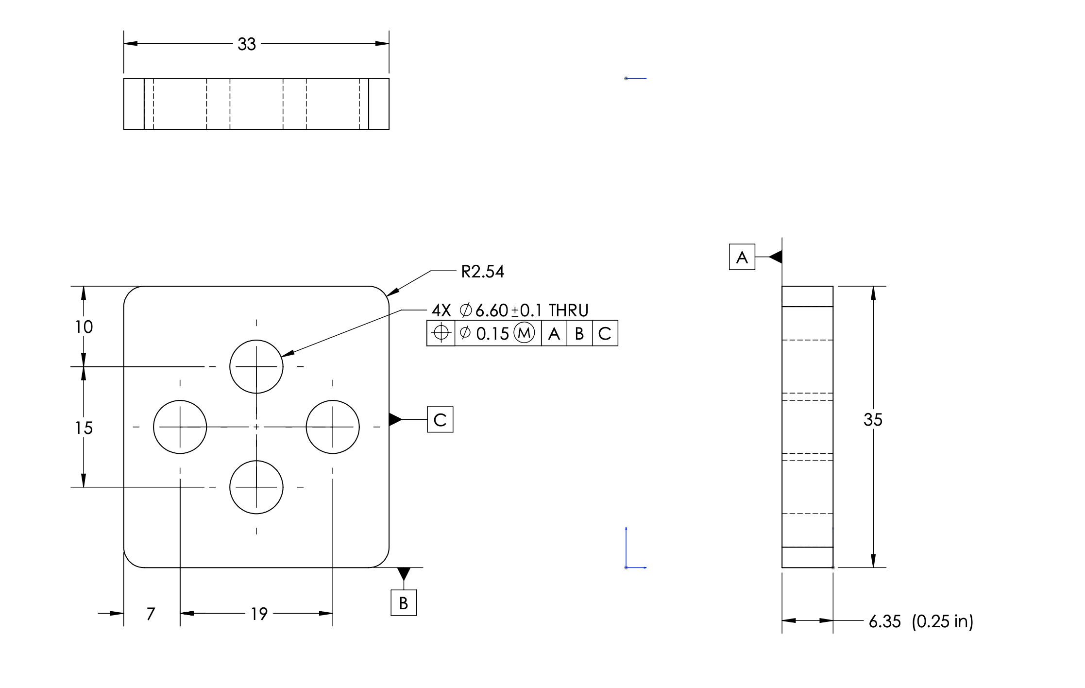
Strain Gage Spacer
- Sandwiched between top plate and strain gage, and bottom plate and strain gage.
- Allows strain gage to flex
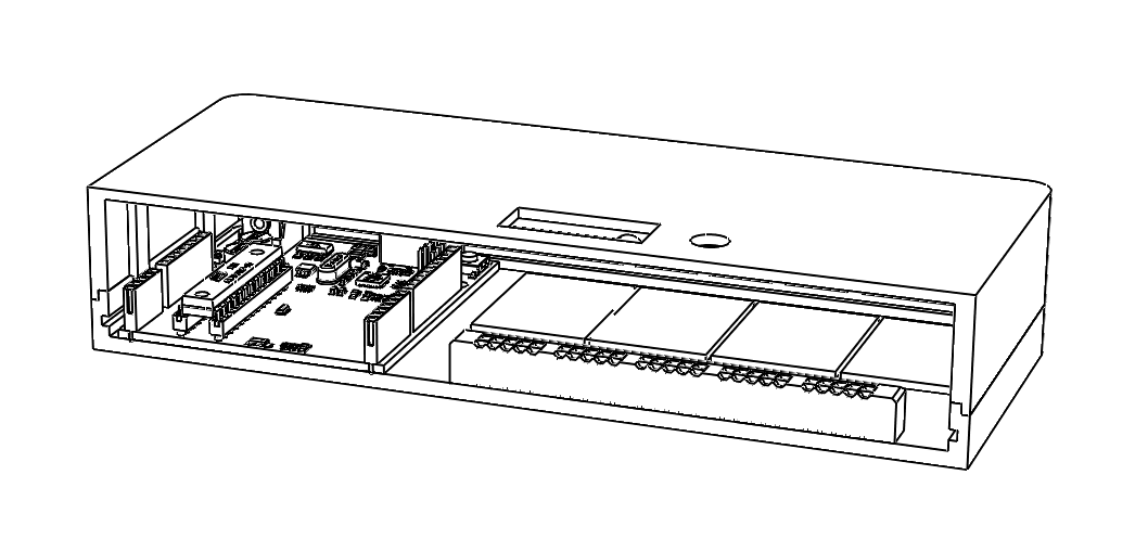
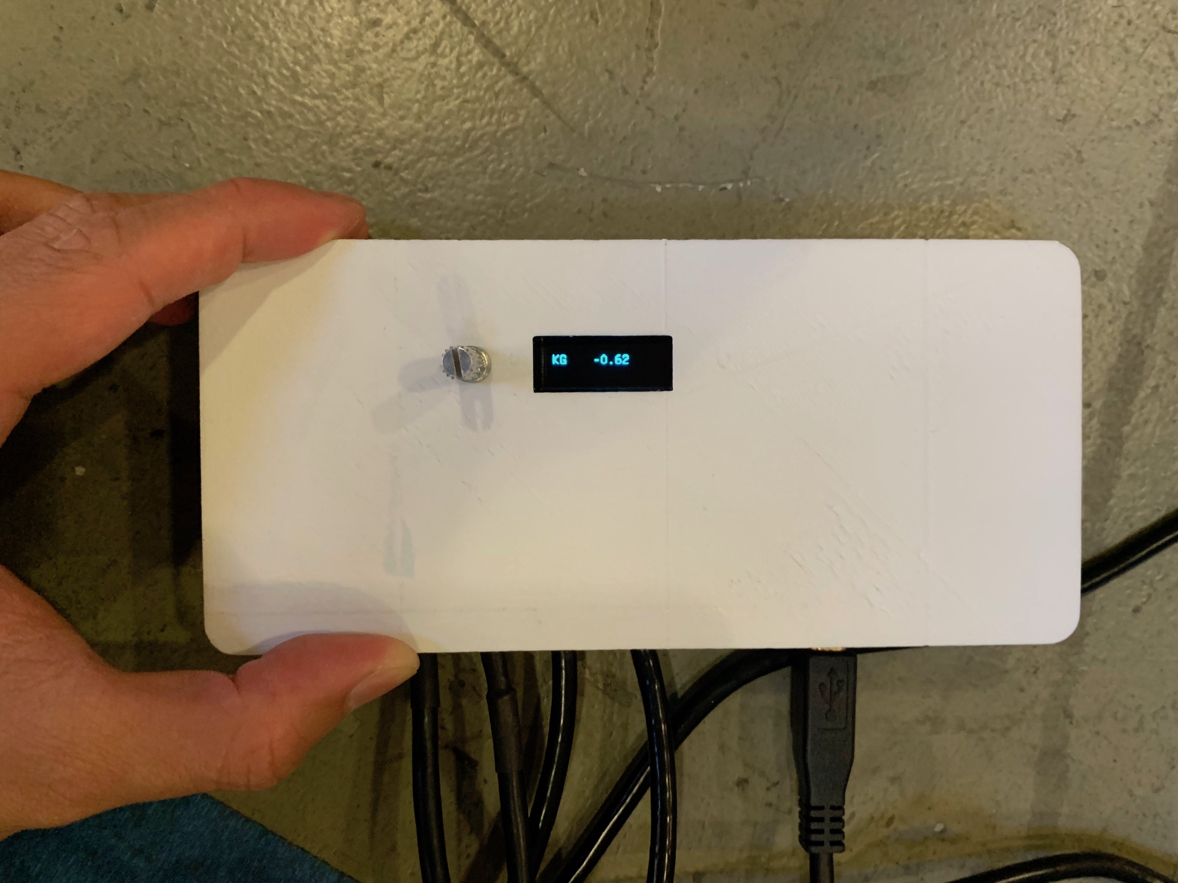
Electronics Box
- 3D printed to hold arduino, wheatstone bridges, OLED screen and control knob
- OLED screen displays COG and mass
- Knob allows for scale to be tared, switch between readings
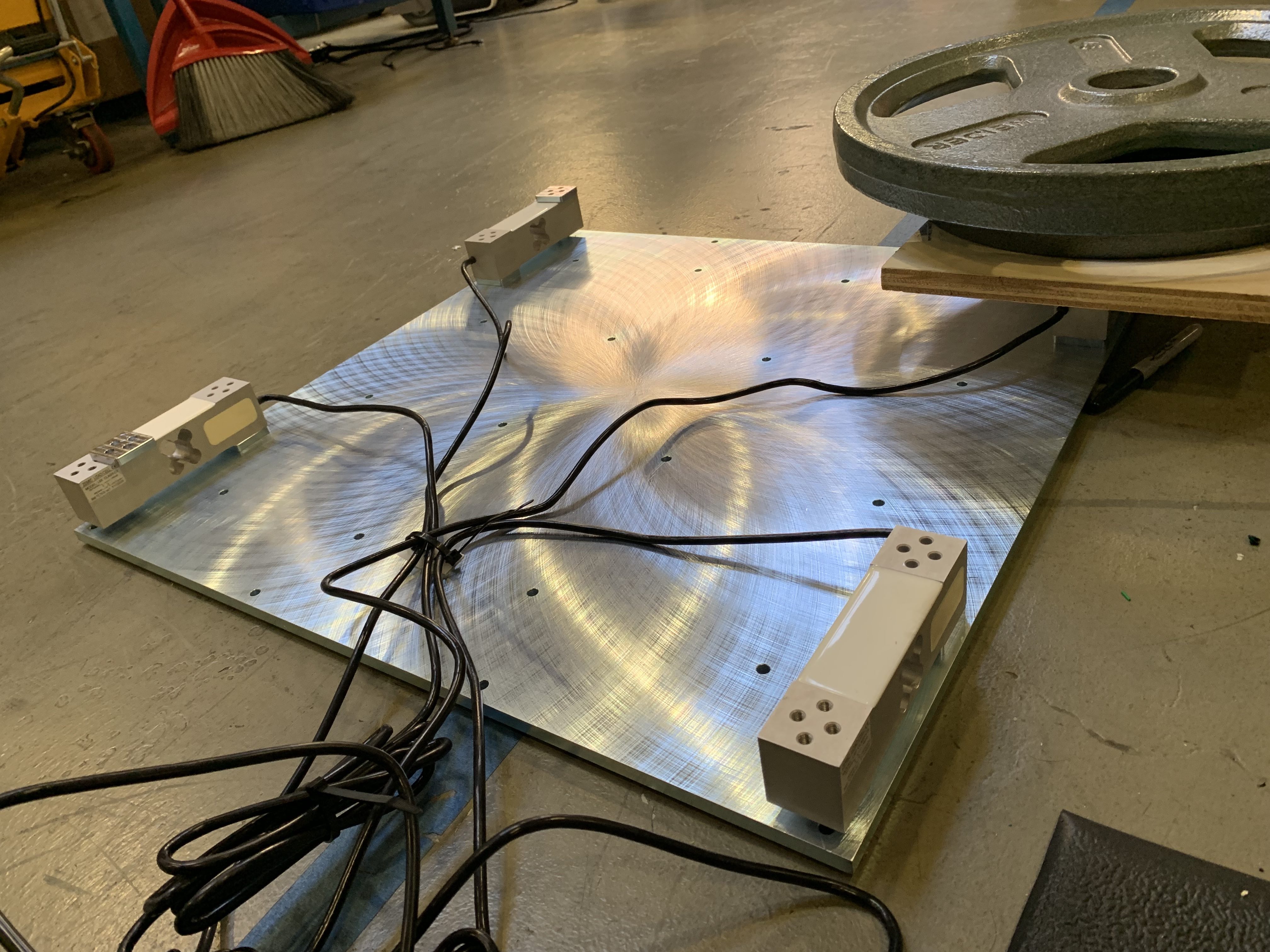
Fabrication
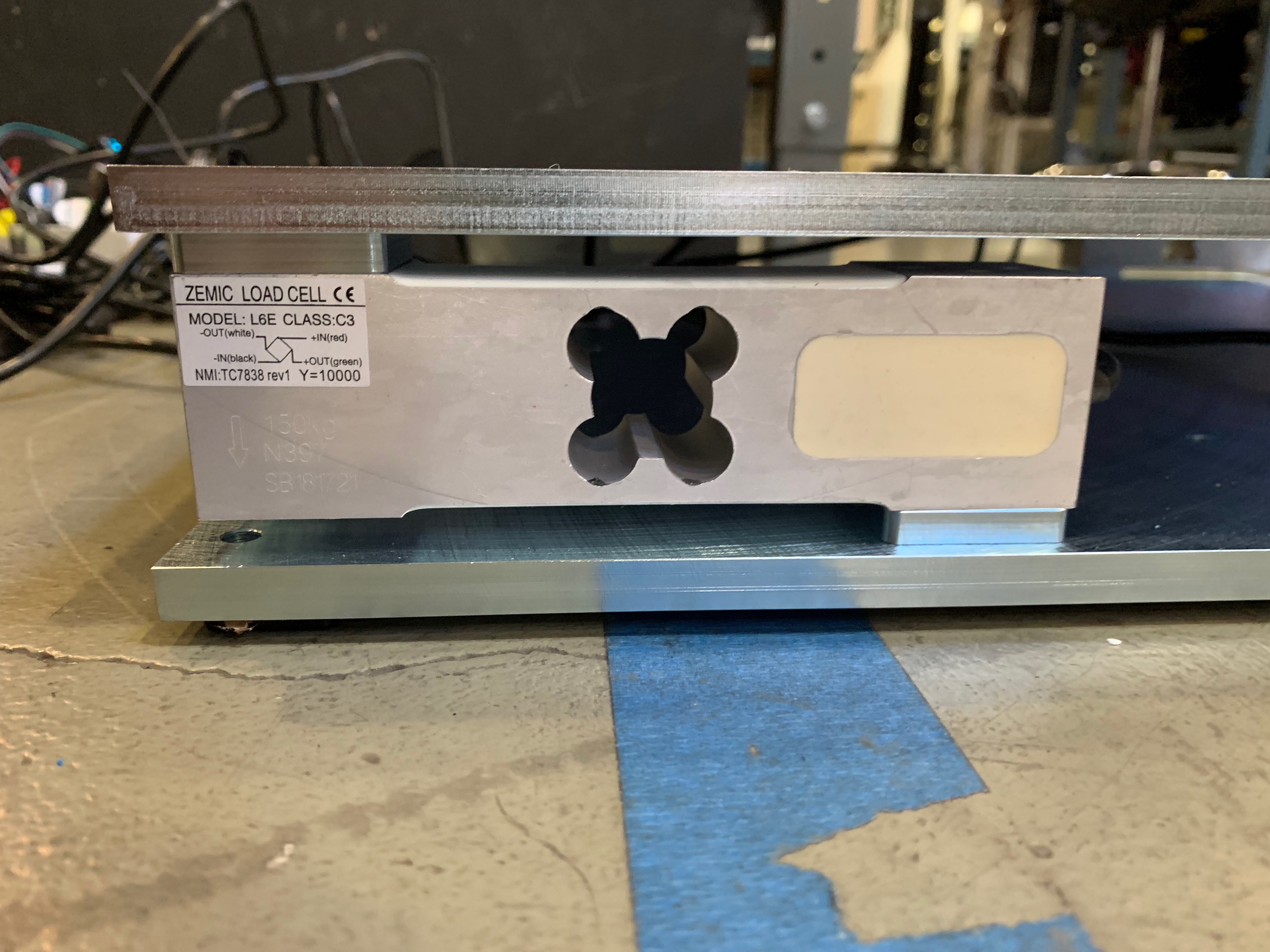
- Each strain gage can support a weight of 150lbs, allowing for a maximum of a 600lbs evenly distributed load.
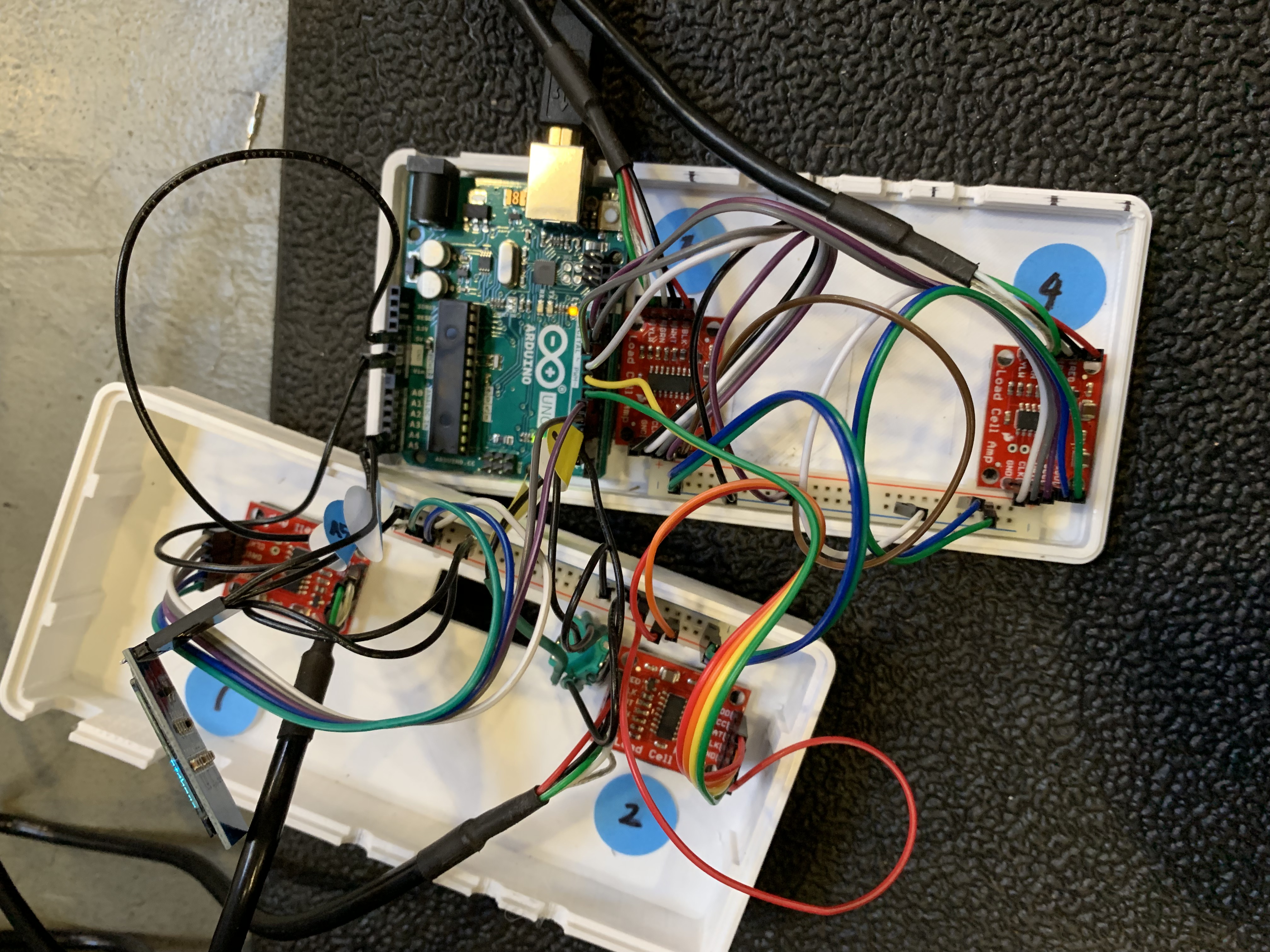
- The strain gages are wired into wheatstone bridges which amplify the analog signal before it is sent into an arduino for processing.
- Arduino outputs the Mass and CoG onto an OLED Screen
Calibration
- Each strain gage needs to be calibrated against a known weight and zero
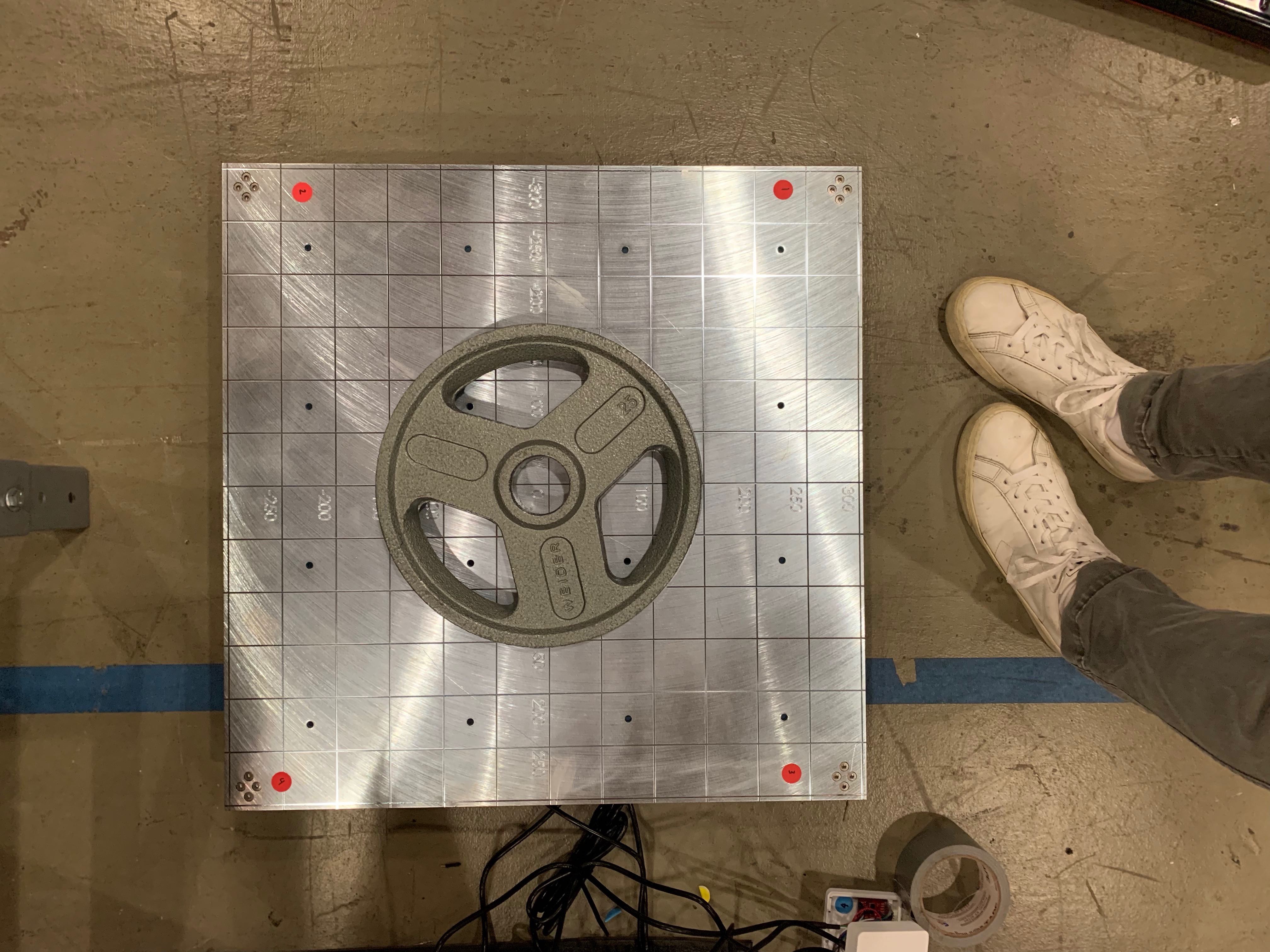
- Once each strain gage was zeroed, the scale was calibrated and tested using a variety of weights
Final Product

Reflection
- Gained additional experience with Arduino and working with sensors and their outputs.
- Applied GD&T to ensure pattern features on parts would assemble.
- Learned to use design requirements to drive research and prototyping.